Step 1
By Vinzenz Unger and Anchi Cheng
Optical diffraction, image acquisition and preparation, determination of lattice parameters, calculation of unit cell dimensions and magnification, calculation of a filtered image
Optical diffraction
Objective:Evaluation of image quality, determination of tilt parameter (see step 5)
If illuminated by coherent light (e.g. laser beam) the images of crystals act as diffraction gratings. Sharp and bright spots that extend far and evenly in all directions are the hallmark of well-ordered crystals. In contrast, large and diffuse diffraction spots or a pattern that only shows a few spots in each direction are signs of disorder. Such crystals may not be suitable for further processing. To obtain reliable results and to avoid potential complications at later stages in the processing the following points are important:
- Analyze the micrograph with the emulsion facing towards the detector (e.g. in a vertical setup this corresponds to the emulsion side facing up).
- Move the micrograph around to identify the largest coherently diffracting area. Ideally, there would be only one coherent area. However, in praxis the following may happen:
spots “jump” while the micrograph is being moved –> more than one independent crystalline area is present. defined spots of multiple lattices are visible –>many small areas or stacked 2D- crystals remedy: decrease size of aperture at optical bench to figure if any one part of the image can be used
- Identify the best area by finding the part of the image for which number, sharpness and intensity of visible diffraction spots is maximal. Clearly mark centre of area by placing marks at the edge of the image. If an image contains two or more good areas that do not overlap, mark and treat them as independent “images”.
- Scanning the best area for further processing sometimes will require including unwanted parts of a neighboring crystalline patch. Keep the “contaminating” area to a minimum. This will be impossible if the two areas are stacked. If the layers are both good, estimate the number of spots that overlap. Do not proceed if this is a significant number because it will be impossible to combine the data.
- Keep a record of the approximate resolution limit observed by optical diffraction. Image processing should provide data to about twice this limit. If this is not the case some processing parameters may need adjustment.
Mainly upon analyzing images of tilted crystals one may encounter an uneven distribution of spots along a preferential axis. Such anisotropic diffraction can be caused by a lack of specimen flatness, specimen movement during the exposure or splitting of spots if the specimen tilt is high. While the first two problems cannot be overcome computationally the splitting of spots observed at high specimen tilts can and needs to be corrected for in the image processing procedure. Accordingly, most images showing anisotropic diffraction (especially at lower specimen tilts) are not suitable for further processing.
Image acquisition
- Calibrate the scanner / microdensitometer using a blank (unexposed) part of the micrograph if possible
- Scan only the best parts of micrographs to keep files reasonably small. Image sizes up to about 6000×6000 pixel can be handled quite comfortably if availability of disk space is not a problem. MRC processing software requires square images as input. This makes arrays in increments of 1000 pixels a convenient choice.
- Scan micrographs with the emulsion side facing the detector (to stay consistent with orientation of film in microscope and optical diffraction). For instance, on a flatbed microdensitometer that has the light source underneath the scanning stage and the detector above the stage the emulsion side should face up.
- Sample densities at at least 1/2 to 1/3 of the frequency required to retain the desired resolution at a given magnification, i.e.
stepzise [µm] ≤ (magnification/ 10.000) * resolution [Å]/2 (1)
- Typical magnifications are at ~60.000x for images of a specimen that diffracts to high resolution. This requires scan step sizes of 5-7µm to retain all the information. In these cases the number of unit cells represented in the scanned part of the image quickly becomes too small for the amplitudes of the high-resolution terms to rise above the background noise of the image (i.e. no phase information can be obtained). This emphasizes why the best area of the micrograph should be chosen carefully.
- Keep a record identifying the corners for start and end of the scan at least initially to be able to identify unwanted changes in the orientation of the image during the acquisition process.
- Retrieve binary image file, convert to MRC-format and visually check for scan artifacts (e.g. purely white or noisy “ghost lines”). Displaying files with MRC-format can be done with the software package XIMDISP (available from the MRC upon request)
Depending on the type of scanner, different routines will be required for the conversion to MRC-format. In cases where the scanner output are transmission values a conversion to optical densities needs to be done before proceeding any further. Precisely what is required needs to be determined by the local user. Furthermore, since machine type and display software will differ between laboratories it cannot be emphasized enough that the apparent orientation of the displayed image should be the same as the orientation of the image on the scanner. For instance, assume that the micrograph is scanned along a normal x,y coordinate system (i.e. x going to the right and y going up). In this case the origin (0,0) of the displayed image should be in the bottom left corner and the last pixel scanned (x,y) should occupy the top right corner on the display. In other words, any two corners on the display must correspond to the same corners on the selected area. However, initially this may not be true in most cases. The MRC-package uses the convention that the image origin (0,0) is at the bottom left corner. Accordingly, the image may need to be rotated or flipped to meet the program requirements. Otherwise, some rules have to be established to determine the correct handedness later on in the processing. Scanning some easily identifiable patterns as test cases is helpful to assure the correct orientation and that the handedness of objects is not altered during the acquisition steps.
Image preparation and determination of lattice parameters
Before submitting the image to the main protocol some “cosmetic” operations should be performed to prepare the image.
- Create a smooth gradient of optical densities around the edges of the image (program: TAPEREDGE). This is necessary because in many cases the optical densities along opposite sides of the image are significantly different. In the calculated transform this leads to pronounced spikes, which may overlap, with some of the low-resolution terms. Any overlap will make it impossible to extract correct amplitude and phase values for these Fourier terms.
- Generate a histogram of the optical densities (program: HISTO) and eliminate extreme densities caused by dust particles, scratches in the negative or unexposed areas (program: LABEL). This step is optional
- Create a smaller copy of the original by pixel averaging if the image is 3000×3000 pixel or larger. This step does not influence the accuracy of the main processing routines but saves disk space and speeds up the steps that can be performed on a reduced copy of the image. In praxis 2×2 pixel averaging (program: LABEL) is advisable and sufficient.
- Calculate the Fourier transform of the tapered and reduced (or tapered original) image (program: FFTRANS) to provide the input for the calculation of a filtered image and to allow the determination of the lattice parameters.
- Display the transform and index several diffraction spots. Avoid reflections that are dispersed or do not fit the lattice well because including these may enforce a worse overall fit for the lattice parameter which does not serve the purpose of this step.
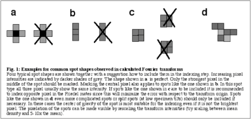
Generally, spots to as high a resolution as possible should be included in the indexing as long as they are unambiguously determined (see Fig.1). Indexing the Friedel mates of the chosen reflections helps to minimize the offset of the fitted lattice from the true transform origin.
- Determine the lattice parameters as precisely as possible. For instance, if ~20-40 spot coordinates are used to fit the lattice vectors (menu option in XIMDISP), the root mean square error for the fit should not exceed 0.5 pixel.
This accuracy is critical to be able to detect and retrieve the weaker high-resolution data. However, it is often impossible to achieve this accuracy for the transforms of uncorrected images especially if the specimen does not diffract to near atomic resolution. In this case a preliminary run through the processing routines under less stringent conditions is helpful to get more precise lattice parameters. Root mean square errors up to about 1- 1.5 pixels are acceptable for this preliminary run. The rough correction of the image usually will sharpen the high-resolution spots enough to allow them being included in the indexing. It is advisable to display the final lattice and check that most of the spots fall onto their predicted positions.
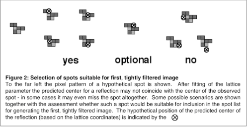
- Make a list of spots suitable for calculating a filtered image while inspecting the outcome of the final lattice fit. Use only those terms for which a “perfect spot” (like shown in Fig.1a) centered around its predicted position would include a significant part of the observed spot (see Fig. 2). This is important if the explicit protocol is used that is given later.
- For reasons outlined in the more detailed explanation for setting the program parameter in MASKTRANA it may not be advantageous to include spots beyond 15Å unless their intensities are high.
Calculation of the unit cell dimensions and magnification
Besides serving as input for subsequent programs the lattice vectors are also used to calculate the unit cell dimensions, the precise magnification of the image and where applicable the overall tilt geometry.
For a new specimen the first step is to determine the real space unit cell dimensions. The transform coordinates for the (1,0) and (0,1) reflections allow to calculate the length of the reciprocal space vectors (a* and b* respectively) which reflects the maximal number of unit cells along these two directions. In XIMDISP this number is given explicitly. If initially the nominal magnification at which the image was recorded is used as estimate then the unit cell size can be calculated as follows:
Similarly the length of the b-axis can be calculated by using the b* value instead of a*. The reciprocal space (γ*) angle needs to be accounted for if different from 90˚ because a* and b* are projections of the real space axes. If the two unit cell axes are not the same the smaller is usually identified with the a-axis (i.e. in reciprocal space this is the longer axis).
Once a reliable average has been determined from several images, above formula can be rearranged to adjust the magnification for all images. The precise magnification is required for a simulation of the so-called contrast transfer function that affects the phase data. Two things need to be pointed out at this stage. First, the magnification of the microscope should be calibrated by taking some images of a test specimen with known unit cell dimensions (e.g. purple membrane or catalase) and second, equation (2) only holds for specimens with tilts below 30˚. For images of crystals at higher tilts a scale factor needs to be included to correct for the observed distortions of the lattice vectors. The required scalefactor is calculated by the program EMTILT, along with the tilt geometry. To calculate the magnification the following equation may be used:
Calculation of a filtered image
Objective: Identify best centre coordinates for future reference area
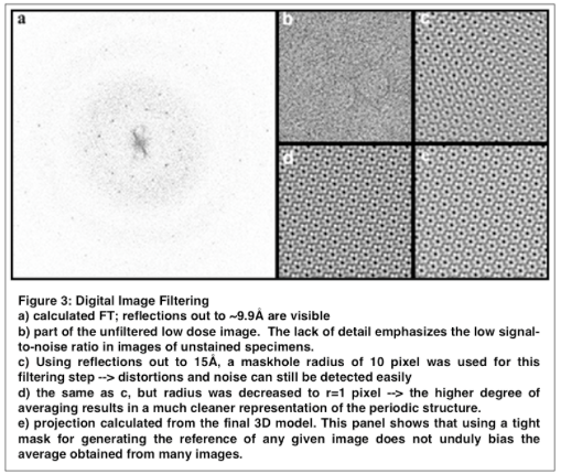
This step takes advantage of the fact that the information about the structure of the protein is contained in discrete diffraction maxima. Consequently, most of the noise can be removed by placing mask holes around the diffraction spots in the transform and zero all remaining values (program: MASKTRANA). The backtransform (program: FFTRANS) yields a filtered image that shows the object much more clearly (see Fig.3). For an ideal and infinite lattice all of the diffraction spots would be so called “delta functions”, i.e. peaks occupying a single pixel only. However, due to the finite size of the image and lattice disorder the real peaks are spread over several pixels. Accordingly, the outcome of the filtering step will largely depend on the size and type of the mask hole used. The smaller the maskhole radius the “nicer” the image will look since decreasing the radius excludes information about the lattice distortions (see Fig. 3). This immediately suggests that distortions can be identified by “comparing” (= cross-correlating) a tightly masked transform (= reference) with a loosely masked transform that still contains all the information about irregularities in the lattice. However, to get the best results one first needs to determine the xy-coordinates that will serve to centre the reference area. If the optical diffraction was done carefully the centre will be close to the actual centre of the digitized array. Nevertheless, checking a filtered image prior to executing the main script is often beneficial, especially for specimens that are not perfectly ordered.
- Tightly mask the transform to produce a mostly uniform image.
- Choose the reference area (1/10 - 1/20 of the size of the filtered image) and keep a record of centre-coordinate for later use.


